1. What is a Chemical Pump?A pump is a machine used to transport liquids and increase their pressure. A chemical pump is a general term referring to pumps with special requirements for chemical production:
(1) Capable of meeting chemical process needs;
(2) Resistant to high and low temperatures;
(3) Corrosion-resistant;
(4) Wear-resistant;
(5) Leak-proof or low-leakage;
(6) Able to transport liquids in critical states;
(7) Reliable operation.
These primarily relate to the characteristics of the medium. Any pump that improves corrosion resistance to chemicals (other than pure water) through material changes or structural modifications is collectively called a chemical pump.
A chemical pump mainly consists of a pump body, impeller, pump cover, and other components.
2. What are the Uses of Chemical Pumps?Chemical pumps are widely used in industrial and urban water supply/drainage, as well as farmland and orchard irrigation/drainage, for transporting clear water or other liquids with physical and chemical properties similar to clear water.
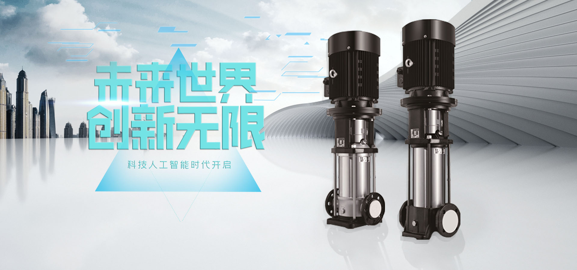
Application Scope of Chemical PumpsSuitable for extracting corrosive liquids from bottles, barrels, cylinders, pools, or other containers.
Feature stable and reliable performance, good sealing, attractive appearance, and convenient maintenance, playing a significant role in improving product quality, reducing leaks, preventing pollution, and protecting the environment.
Applicable for transporting corrosive media at various temperatures or media with high physical/chemical properties in sectors such as chemicals, petroleum, metallurgy, power stations, food, pharmaceuticals, and synthetic fibers.
Main products include various fiberglass chemical pumps, corrosion-resistant plastic pumps, high-temperature chemical pumps, standard chemical process pumps, and magnetic drive pumps.
Used for pumping clear water, abrasive substances harmful to ordinary pump materials, suspended matter, corrosive substances to stainless steel, and non-explosive materials.
Widely used in water supply systems.
Applied in heating, air conditioning, cooling, and circulation systems.
Used for civil and industrial purposes.
Used in fire protection systems.
Used for irrigation.
Used for daily, civil, industrial, horticultural, and irrigation purposes.
Used in rainwater harvesting projects.
Suitable for low-noise environments.
Used for pressure boosting, suitable for transporting corrosive, explosive, or particulate-laden water/liquids.
Suitable for pipeline network pressure boosting.
3. Classification of Chemical PumpsClassification by MaterialStainless steel chemical pumps: Widely used in petroleum, chemicals, metallurgy, synthetic fibers, pharmaceuticals, food, etc., for transporting alkaline corrosive media.
Fluoroplastic chemical pumps: Used for transporting any acidic or alkaline corrosive media.
Cast iron chemical pumps: Used for industrial and urban water supply/drainage, as well as farmland and orchard irrigation/drainage, for transporting clear water or similar liquids.
Classification by PurposeProcess pumps: Including feed pumps, reflux pumps, circulation pumps, flush pumps, sewage pumps, makeup pumps, and output pumps.
Utility pumps: Including boiler pumps, cooling tower pumps, fire pumps, and deep well pumps for water sources.
Auxiliary pumps: Including lubricating oil pumps, seal oil pumps, and hydraulic transmission pumps.
Pipeline transport pumps: Oil pipeline pumps and loading/unloading pumps.
Classification by Working Principle and StructureVane pumps: Transfer liquids to pipelines or containers via centrifugal or axial forces generated by impeller blades rotating with the pump shaft (e.g., centrifugal pumps, vortex pumps, mixed-flow pumps, axial-flow pumps).
Positive displacement pumps: Transport liquids through continuous changes in the volume of the pump cylinder (e.g., reciprocating pumps, piston pumps, gear pumps, screw pumps).
Other types: Electromagnetic pumps using electromagnetic force to transport liquid conductive media; pumps using fluid energy (e.g., jet pumps, air lift pumps).
Classification by Transported MediumWater pumps: Including clear water pumps, boiler feed pumps, condensate pumps, and hot water pumps.
Corrosion-resistant pumps: Including stainless steel pumps, high-silicon cast iron pumps, ceramic acid-resistant pumps, impervious graphite pumps, hard rubber-lined pumps, rigid PVC pumps, canned pumps, diaphragm pumps, and titanium pumps.
Slurry pumps: Including slurry pumps, sand pumps, sewage pumps, coal powder pumps, and ash slurry pumps.
Oil pumps: Cold oil pumps, hot oil pumps, submersible oil pumps, oil slurry pumps, and liquid hydrocarbon pumps.
Classification by Operating ConditionsHigh-flow and micro-flow pumps: Flows of 300 m³/min and 0.01 L/min, respectively.
High-temperature and low-temperature pumps: High temperatures up to 500°C, low temperatures down to -253°C.
High-pressure and low-pressure pumps: High pressure up to 200 MPa, vacuum degrees of 2.66–10.66 kPa (20–80 mmHg).
High-speed and low-speed pumps: High speeds up to 24,000 r/min, low speeds of 5–10 r/min.
Precision metering pumps: Flow metering accuracy up to ±0.3%.
High-viscosity pumps: Viscosity up to thousands of pascal-seconds (Pa·s).
4. Working Principles of Chemical PumpsNegative Pressure PumpsBefore starting, the suction pipe and pump must be filled with liquid. After starting, the impeller rotates at high speed, and the liquid inside rotates with the blades. Under centrifugal force, the liquid is thrown outwards from the impeller, slowing down in the pump casing’s diffuser chamber and increasing in pressure before flowing out through the pump outlet and discharge pipe. At this time, a vacuum low-pressure zone (devoid of air and liquid) forms at the blade center due to the liquid being 甩出 (flung out). Liquid in the reservoir is drawn into the pump through the suction pipe under atmospheric pressure, continuously feeding the pump and discharging through the outlet.
Positive Pressure PumpsPrimarily referring to submersible pumps (e.g., gas station submersible pumps and long-shaft submersible pumps):
Submersible pumps immerse the motor and pump together at the tank bottom, where the motor drives the impeller to pressurize and push the medium to the ground target.
Long-shaft submersible pumps separate the pump and motor, connecting them with a long shaft. They use positive pressure to transport the medium, solving air blockage and impeller cavitation issues caused by negative pressure transport.
Submersible pump motors are submerged below the liquid level, integrated with the pump wheel. Key advantages include a short pump shaft (only hundreds of millimeters), no long-shaft swing, stable operation, low noise, and minimal wear.
Sealing Types for Chemical Pumps: Oil seal, gasket seal, thread seal, labyrinth seal, packing seal, dynamic seal, and mechanical seal.
5. Installation PrecautionsWhat should be noted when installing chemical pumps? Below are key installation considerations:
Prepare a concrete foundation according to the foundation dimensions and embed anchor bolts in advance.
Inspect the pump and motor before installation to ensure all parts are intact and the pump interior is free of debris.
Place the unit on the foundation and use wedge pads between the baseplate and foundation to level the pump. Tighten anchor bolts after leveling.
The suction and discharge pipelines of the pump must have supports and should not be supported by the pump itself. The diameters of the inlet/outlet pipes should match the pump’s inlet/outlet.
For FZB series self-priming pumps, connect the inlet pipe first, fill with liquid, then connect the outlet pipe, and check the rotation direction. The inlet pipeline must match the pump and have a total length of no more than 5 meters to avoid affecting self-priming performance. The self-priming height can be roughly calculated as: Self-priming height for clear water (3m) / medium density = actual self-priming height.
After installation, manually rotate the coupling to check for rubbing. Smooth and uniform rotation indicates successful installation.
Magnetic pumps are strictly prohibited from pumping particulate or easily crystallized media and cannot operate continuously with the discharge port closed; minimum flow must be maintained.
Install a filter at the inlet to prevent debris from entering the pump. The filter area should be 3–4 times the pipeline cross-sectional area.
For high-head pumps, install a check valve on the outlet pipeline to prevent water hammer damage from sudden shutdowns.
Ensure the pump’s installation height complies with its net positive suction head (NPSH) requirements, considering pipeline losses and medium temperature.
When the medium temperature is too high, cool the mechanical seal to prevent deformation and static ring cracking.
If the medium viscosity is too high, pump performance and power consumption will change; contact the manufacturer for details.
6. Startup and Operation of Chemical PumpsBefore starting, fill the pump with the liquid to be transported (for suction-type pumps), close the outlet gate valve, and connect the power supply.
Turn on the power and check the pump’s rotation direction.
Run the unit for 5–10 minutes for testing. If no abnormalities occur, it can be put into operation.
When stopping, close the outlet gate valve first, then cut off the power supply.
7. Maintenance of Chemical PumpsRegularly inspect the pump and motor, and replace wearable parts.
When out of use for an extended period, clean the pump’s flow path and disconnect the power supply.
Never operate the pump without liquid (dry run).
Tips: What pump to choose for weakly corrosive media?
Question: We need to transport a 5% dilute sulfuric acid at ~20°C, which is weakly corrosive. What pump should we choose?
Answer: A stainless steel (304) pump is suitable. Stainless steel pumps can transport media within the following range:
If your medium is listed as compatible, consider:
CQ-type stainless steel magnetic drive pumps
IH-type stainless steel chemical centrifugal pumps
If your medium is incompatible, consider more corrosion-resistant materials:
Engineering plastic (reinforced polypropylene)
Ultra-high molecular weight polyethylene (UHMWPE)
Fluoroplastics (PTFE, FEP)
8. Causes and Diagnosis of Mechanical Seal Leaks in Chemical PumpsMechanical seals are a type of dynamic seal for rotating parts. With appropriate flushing schemes, they can achieve minimal or zero leakage (gas/liquid sealing media may enter the process medium).
Principle of Mechanical SealsA mechanical seal consists of at least one pair of end faces perpendicular to the rotation axis, kept in close contact and relative sliding under fluid pressure and compensating mechanism force (or magnetic force), with auxiliary seals to prevent fluid leakage.
For a typical single-spring single-end mechanical seal, the spring is compressed after proper installation. When the pump starts, the right-side components rotate with the shaft, while the left-side components remain stationary. The end faces of the hot-set static ring and dynamic ring 贴合 (contact) under spring force for relative motion.
Mechanical seals, also called face seals, primarily rely on the frictional sealing of static and dynamic ring end faces. They offer better sealing, less leakage, longer lifespan, and lower power consumption than packing seals but are more complex to manufacture, require high precision, are costly, and demand skilled installation.
Floating Ring SealsFloating ring seals use the end faces of floating rings and floating sleeves (support rings) under liquid pressure and spring force (some designs omit springs) to achieve radial sealing. Liquid can only pass axially through the narrow gap between the floating ring and shaft (or shaft sleeve). Axial sealing is achieved by reducing pressure through throttling in the narrow gap between the shaft’s outer surface and the floating ring’s inner surface. Hydrodynamic support allows the floating ring to self-center, ensuring reliable operation with leakage between the two sealing types. This seal is typically used under high temperature and pressure.
Causes and Diagnosis of Mechanical Seal LeaksA. Leakage During Static Testing After Installation
After installing and adjusting the mechanical seal, conduct static testing to observe leakage:
B. Leakage During Commissioning
After static testing, high-speed rotation during commissioning generates centrifugal force, which may suppress leakage. If leakage occurs after excluding shaft and end cover seal failures, the dynamic-static ring friction pair is typically damaged.
C. Factors Causing Friction Pair Seal Failure
Abnormal conditions during operation (e.g., cavitation, air binding, pressure surges) generate large axial forces, separating the dynamic and static ring faces.
Excessive compression during mechanical seal installation, leading to severe wear or scratches on the friction faces.
Too-tight dynamic ring O-ring, preventing axial movement of the dynamic ring.
Loose static ring O-ring, causing the static ring to detach from its seat during dynamic ring movement.
Particulate matter in the medium entering the friction pair and damaging the sealing faces.
Improper design or selection (e.g., low face pressure or large cold shrinkage of seal materials).
Most issues require disassembly and seal replacement, though minor adjustments (e.g., static ring seat alignment) may resolve some problems.
D. Sudden Leakage During Normal Operation
Sudden leakage in centrifugal pumps is rarely due to normal wear or service life and usually stems from significant process changes or improper operation/maintenance:
Cavitation, air binding, or prolonged pressure surges damaging the seal.
Low actual pump output causing excessive internal circulation, heat buildup, and 介质气化 (medium vaporization), leading to seal failure.
High recirculation volume stirring up sediment at the bottom of suction containers, damaging the seal.
Failure to manually rotate the pump after prolonged shutdown, causing adhesion and damage to the friction faces.
Increased corrosive, polymerizable, or gelatinous substances in the medium.
Drastic changes in ambient temperature.
Frequent process changes or adjustments.
Sudden power outages or equipment failures.
Prompt attention and measures are crucial to avoid major accidents or losses.
Tips: How to Extend Service Life?To ensure normal pump operation, develop daily inspection and maintenance habits to avoid issues and improve efficiency. Regular maintenance is essential and should not be overlooked.
Environmental Quality:
Although China is continuously improving pump operating environments, some pumps are still placed in poor conditions. In such cases, frequent cleaning, inspection, and maintenance are necessary, even for highly automated pumps.




